THANK YOU FOR YOUR ORDER
Let’s get you
set up
Pick the part you received for its setup and care guide. Orders, shipping and everything else are further down.
For an existing purchase, message us through your Etsy order.
YOUR PRODUCT
Which one did you get?
Choose yours for setup steps, fit checks and care.
Cooling
Inside the build
Desk & setup
Product setup & care
Setup steps, fit checks and care for every design.
Cooling
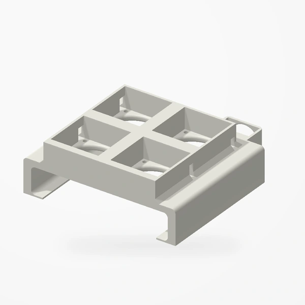
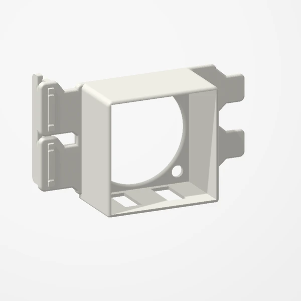
EliteDesk 800 Mini Fan Mount
Before you order
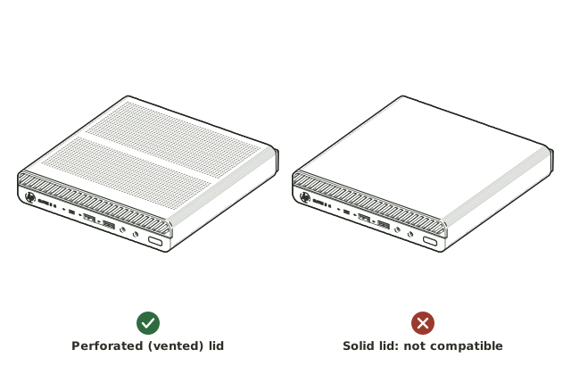
- Compatible only with HP EliteDesk 800 G-series Mini models with the perforated (vented) lid. It does not fit the solid lid.
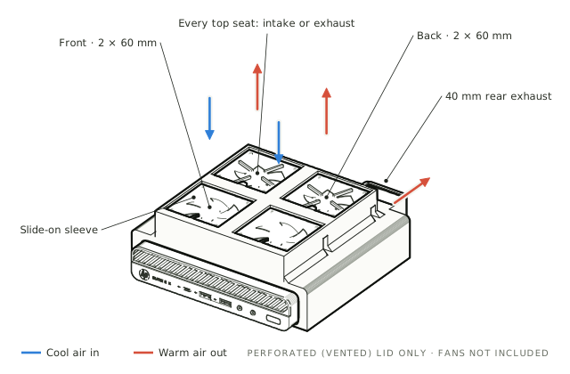
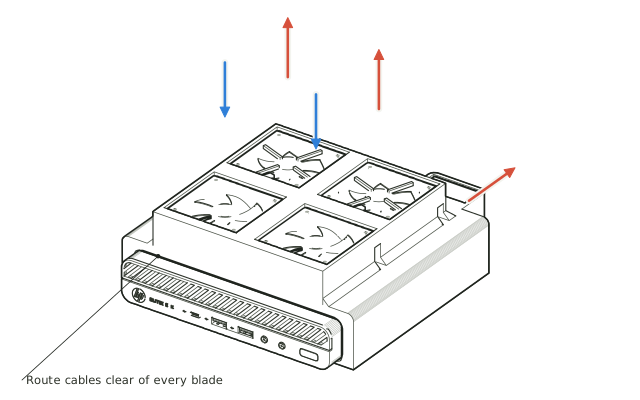
- Fan configuration: up to 4 × 60 mm fans up to 25 mm thick on top, plus 1 × 40 × 40 × 20 mm fan at the rear. Each top seat can run its fan as an intake or an exhaust, and you can start with fewer fans. Fans are not included.
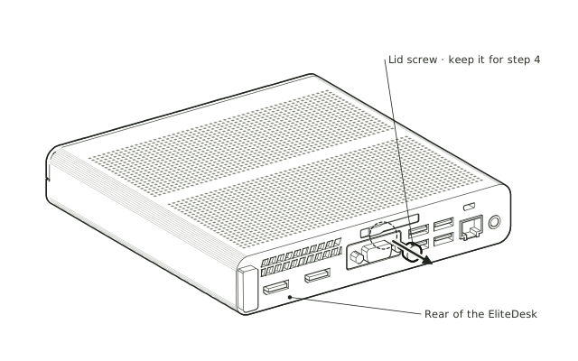
- The sleeve is a precise, made-to-measure slide-on fit over the lid and both sides; the rear tab uses the EliteDesk’s existing lid screw.
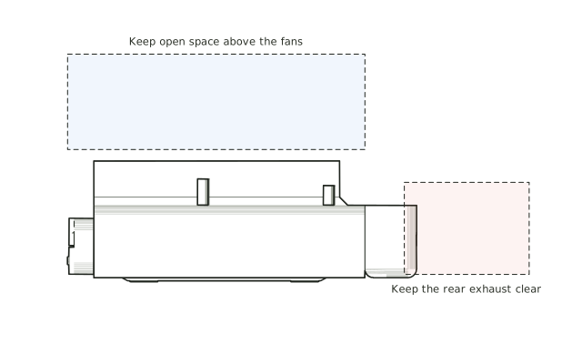
- Leave open space above the top fans and behind the rear exhaust. Avoid shelves, walls or cables that block them.
Compatible only with HP EliteDesk 800 G-series Mini models with the perforated (vented) lid; it does not fit the solid lid. Accepts four 60 mm fans up to 25 mm thick and a 40 × 40 × 20 mm rear fan. In our own stress tests (11 HWiNFO runs with all six cores at 100%, inside a closed drawer), the five-fan mount compared with stock: NVMe drive 61.0°C → 42.0°C peak (−19.0°C, −31.1%) and chipset 62.0°C → 49.0°C (−13.0°C, −21.0%). Compared with our legacy four-fan mount, the CPU peak fell from 82.0°C to 73.0°C (−9.0°C, −11.0%), with no thermal throttling. Results vary by hardware, fans and workload; improvements are not guaranteed. Preview airflow and the perforated lid are illustrative.
Setup & use
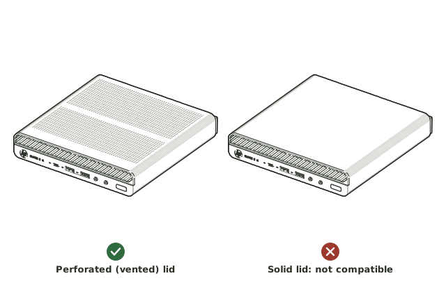 Step 1
Check the lid
Make sure your EliteDesk 800 G-series Mini has the perforated (vented) lid. The sleeve does not fit the solid lid.
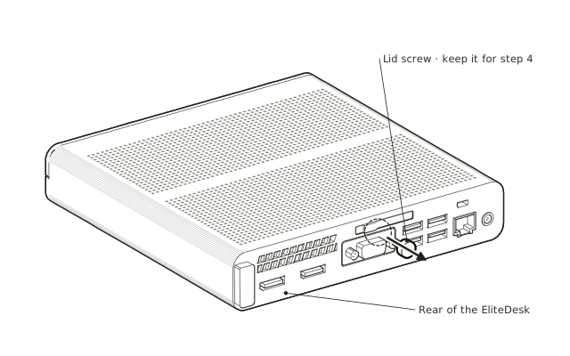 Step 2
Power down and remove the lid screw
Shut down the EliteDesk and disconnect power. Remove the screw at the rear of the lid and keep it for step 4.
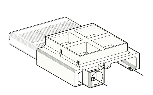 Step 3
Slide the sleeve on from the rear
From the rear, slide the sleeve forward over the lid until the rear tab sits against the back of the case. It is made to measure, so it starts tight: a little wiggle gets it going, then it slides on more smoothly the further it goes.
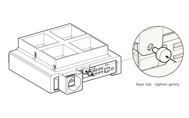 Step 4
Secure the rear tab
Refit the same lid screw through the rear tab. Tighten gently; do not overtighten.
 Step 5
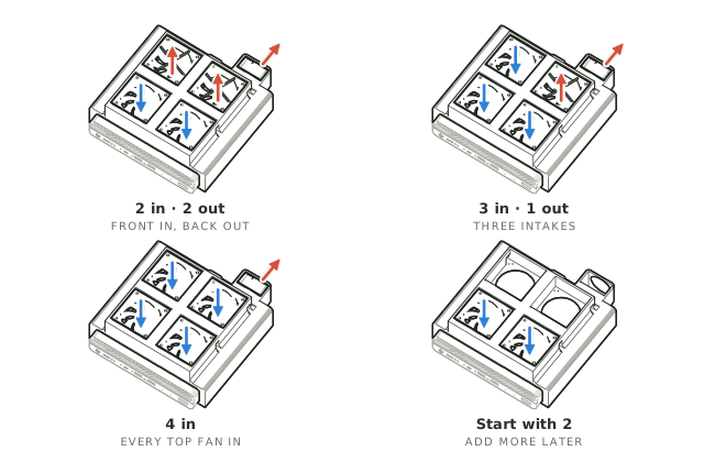
Choose your fan layout
Each of the four 60 mm top seats can run its fan as an intake (blowing down into the case) or an exhaust (blowing up and out), and the 40 mm rear seat exhausts out of the back. Two in and two out is a balanced start; three in and one out, or all four in, push more cool air into the case. You can also start with two fans and add the rest later.
 Step 6
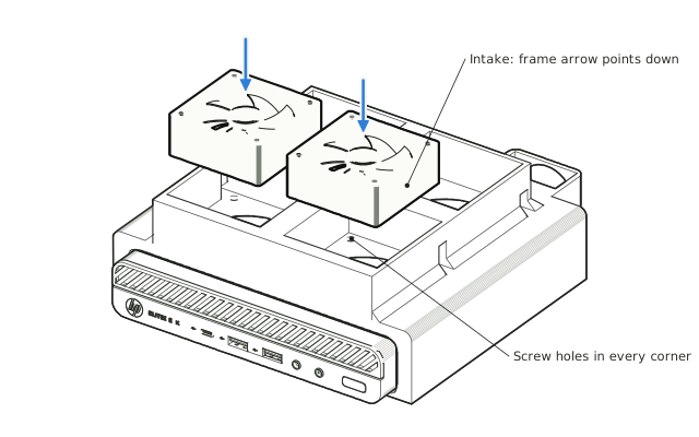
Fit the two front fans
Seat a 60 mm fan (up to 25 mm thick) in each front seat. For intake, its frame arrow points down, blowing into the case. Secure each fan with the screws that came with it, through the four corner holes.
 Step 7
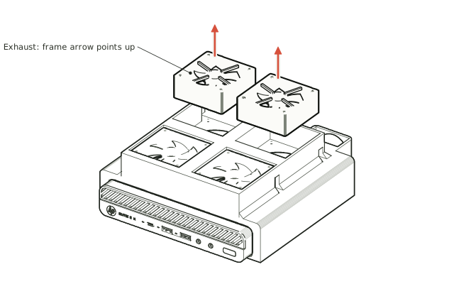
Fit the two back fans
Seat the back two 60 mm fans the same way and screw them in. For exhaust, the frame arrow points up so the fan blows up and out; turn a fan over to make it an intake if your layout calls for it.
 Step 8
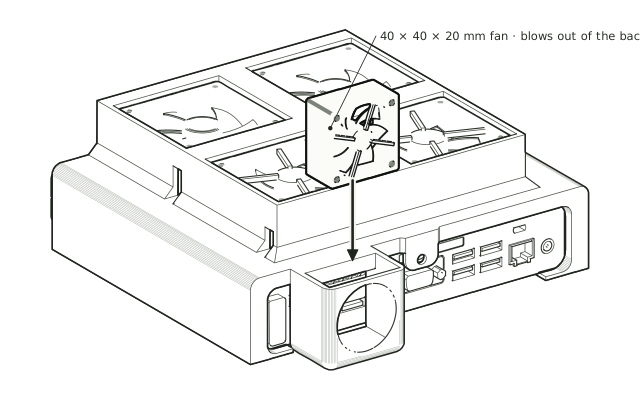
Drop in the 40 mm rear fan
Drop the 40 × 40 × 20 mm fan into the rear pocket from the top so it exhausts out of the back, away from the stock grille.
 Step 9
Connect the fans and check them
Route and connect the fan cables clear of all blades, following each fan manufacturer’s instructions. Check every blade turns freely before switching on.
 Step 10
Leave room to breathe
Leave open space above the top fans and behind the rear exhaust. Avoid shelves, walls or cables that block them.
Drawn from the product’s 3D models. Fans, the lid screw and the lid perforations are illustrative; drawings are not measured plans. Fans are not included.
Have the legacy four-fan version? Its setup steps
The first version has three 60 mm pockets (two front intakes, one back-right exhaust) and the same 40 mm rear seat. It fits, slides on and is secured exactly like the five-fan version. In our tests the five-fan version ran cooler than the legacy mount on every reading (test 9 vs. test 10): CPU peak 82.0°C → 73.0°C (−9.0°C), chipset 54.0°C → 49.0°C, NVMe drive 47.0°C → 42.0°C.
 Step 1
Check the lid
Make sure your EliteDesk 800 G-series Mini has the perforated (vented) lid. The sleeve does not fit the solid lid.
 Step 2
Power down and remove the lid screw
Shut down the EliteDesk and disconnect power. Remove the screw at the rear of the lid and keep it for step 4.
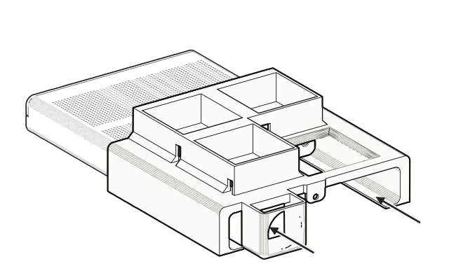 Step 3
Slide the sleeve on from the rear
From the rear, slide the sleeve forward over the lid until the rear tab sits against the back of the case. It is made to measure, so it starts tight: a little wiggle gets it going, then it slides on more smoothly the further it goes.
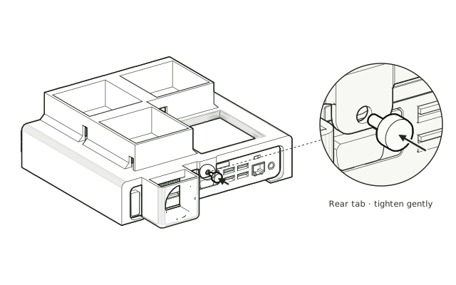 Step 4
Secure the rear tab
Refit the same lid screw through the rear tab. Tighten gently; do not overtighten.
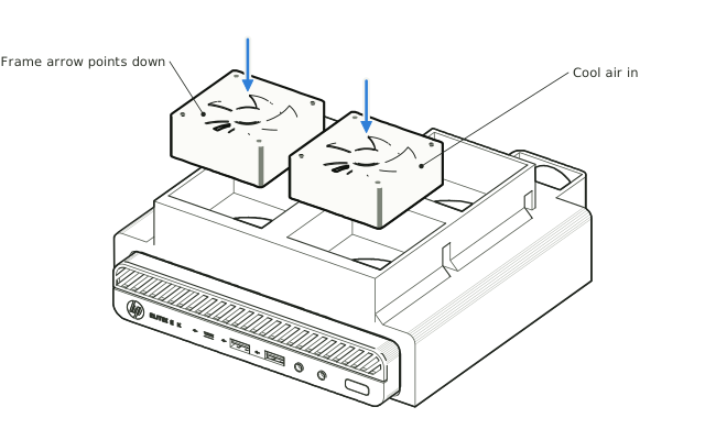 Step 5
Fit the two front intake fans
Seat a 60 mm fan (up to 25 mm thick) in each front pocket as an intake, blowing down into the case. The airflow arrow on each fan frame should point down.
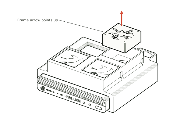 Step 6
Fit the rear-right exhaust fan
Seat the third 60 mm fan in the rear-right pocket as an exhaust, blowing up and out. Its frame arrow should point up.
 Step 7
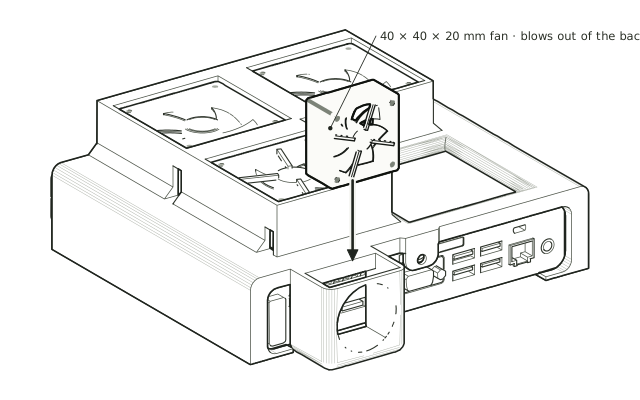
Drop in the 40 mm rear fan
Drop the 40 × 40 × 20 mm fan into the rear pocket from the top so it exhausts out of the back, away from the stock grille.
 Step 8
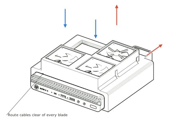
Connect the fans and check them
Route and connect the fan cables clear of all blades, following each fan manufacturer’s instructions. Check every blade turns freely before switching on.
 Step 9
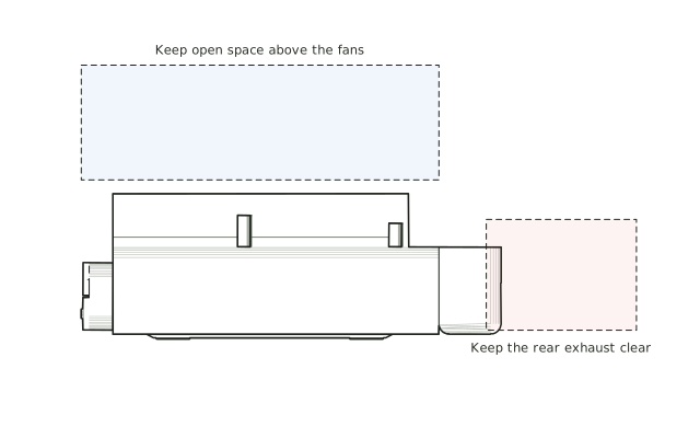
Leave room to breathe
Leave open space above the top fans and behind the rear exhaust. Avoid shelves, walls or cables that block them.
Care & troubleshooting
Wipe with a soft, slightly damp cloth, then dry. Avoid solvents and hot-water cleaning. Dust the fans and lid perforations regularly; blocked intakes reduce airflow. If you notice vibration or blade contact, power down and recheck fan seating, fan screws and cable routing.
Explore this design · Product page · Ask about fit · Coming soon to Etsy
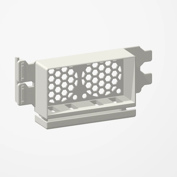
Dual 40 mm PCIe Fan Mount
Before you order
- Fan configuration: 2 × 40 mm. Fans are not included.
- Requires 2 free expansion-slot positions.
- Check case profile against the listing.
- Measure fan thickness and the full assembly clearance beneath the GPU and around nearby cards/cables. Compare with the listing dimensions.
Our tested 2×40 mm configuration reduced GPU temperature by 1.5°C. GPU fan noise also decreased in our test (not measured in dB). Best suited to tighter cases with limited existing airflow. Results vary by case, hardware, fans and test conditions; temperature and noise improvements are not guaranteed. Check fan thickness and clearance around the GPU. Preview airflow is illustrative.
Setup & use
 Step 1
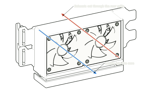
Choose intake or exhaust
Decide which way the fans will blow: exhaust pushes warm air out through the rear grille, intake draws cool air in toward the graphics card above.
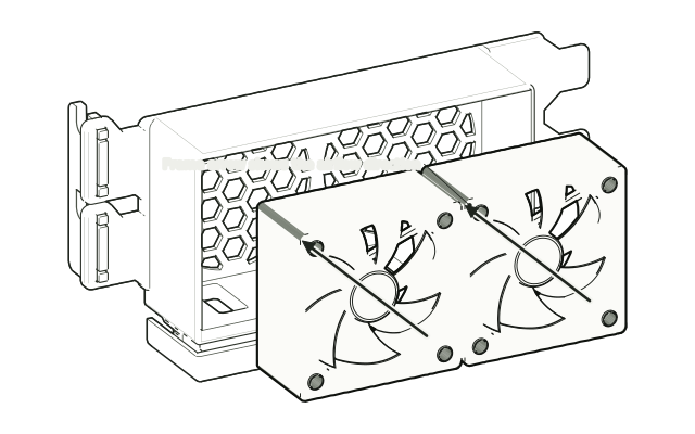 Step 2
Seat the fans
Place the 40 mm fans into the box with the frame arrow pointing the way you chose. Fans are not included.
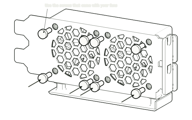 Step 3
Screw them in from the grille side
From the grille side, fix each fan through the four corner holes with the screws (or rubber mounts) that came with the fan. No screws are included.
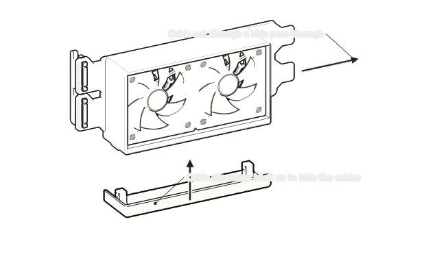 Step 4
Route the cables
Lead each fan cable out through a side pass-through so it stays clear of the blades. Snap the cable clip back on underneath to hide them.
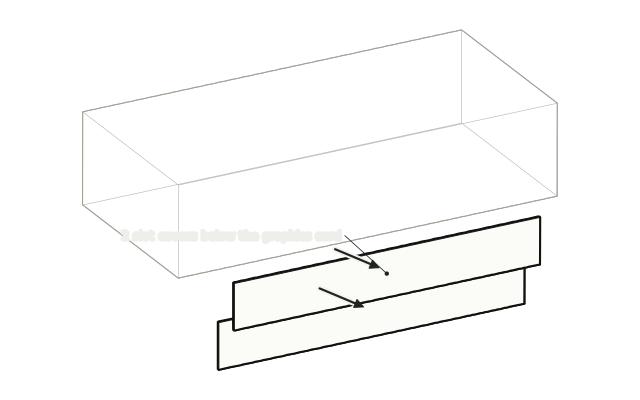 Step 5
Remove the slot covers
Shut down and unplug the PC. Remove the case screws and the 2 slot covers below the graphics card. Keep the screws.
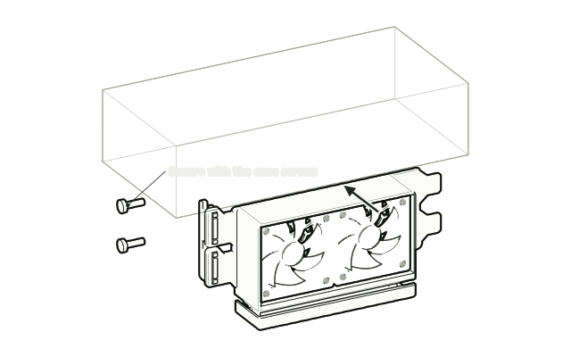 Step 6
Fit it like a card
Slide the mount into the free slots the same way as an expansion card and secure it with the case screws you removed.
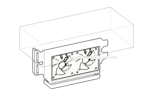 Step 7
Connect and check
Connect each fan to a fan header following its manufacturer’s instructions, check the blades turn freely and nothing touches the graphics card, then power on.
Drawn from the product’s 3D models. Cases, desks, devices and other surroundings are illustrative; drawings are not measured plans.
Care & troubleshooting
Wipe with a soft, slightly damp cloth, then dry. Avoid solvents and hot-water cleaning. If you notice vibration or contact, power down and recheck mounting and cable routing.
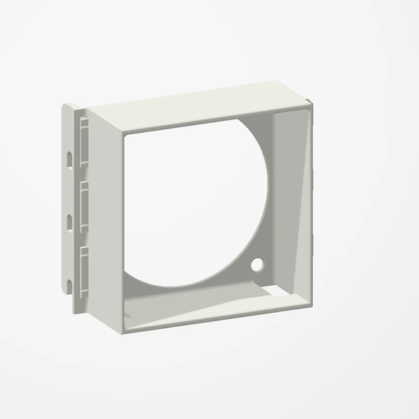
Low-Profile 60 mm PCIe Fan Mount
Before you order
- Fan configuration: 1 × 60 mm. Fans are not included.
- Requires 3 free expansion-slot positions.
- Low-profile cases supported.
- Measure fan thickness and the full assembly clearance beneath the GPU and around nearby cards/cables. Compare with the listing dimensions.
Our tested 1×60 mm configuration reduced GPU temperature by 3°C. GPU fan noise also decreased in our test (not measured in dB). Best suited to tighter cases with limited existing airflow. Results vary by case, hardware, fans and test conditions; temperature and noise improvements are not guaranteed. Check fan thickness and clearance around the GPU. Preview airflow is illustrative.
Setup & use
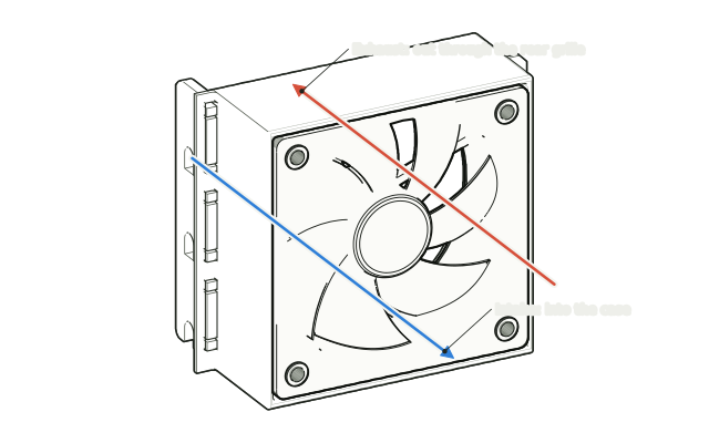 Step 1
Choose intake or exhaust
Decide which way the fan will blow: exhaust pushes warm air out through the rear grille, intake draws cool air in toward the graphics card above.
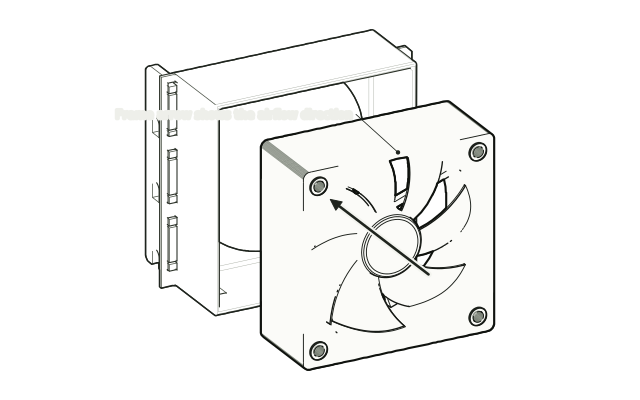 Step 2
Seat the fan
Place the 60 mm fan into the box with the frame arrow pointing the way you chose. A fan is not included.
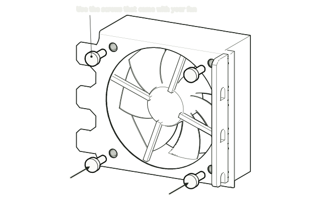 Step 3
Screw it in from the grille side
From the grille side, fix the fan through the four corner holes with the screws (or rubber mounts) that came with it. No screws are included.
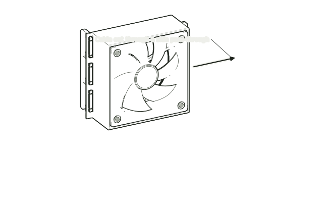 Step 4
Route the cable
Lead the fan cable out through a side pass-through so it stays clear of the blades.
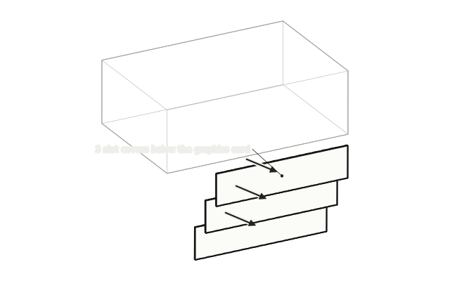 Step 5
Remove the slot covers
Shut down and unplug the PC. Remove the case screws and the 3 slot covers below the graphics card. Keep the screws.
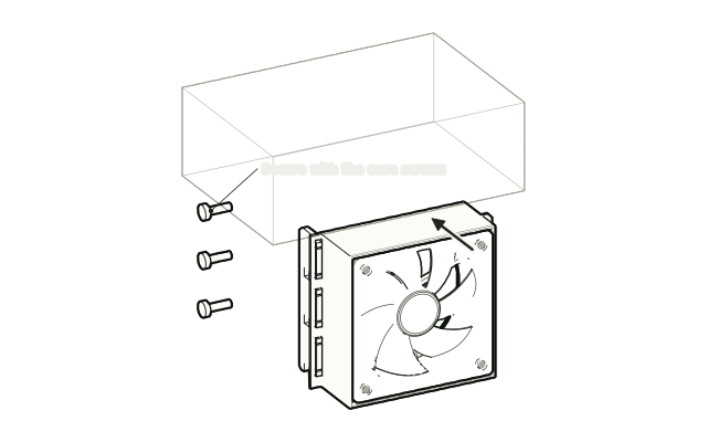 Step 6
Fit it like a card
Slide the mount into the free slots the same way as an expansion card and secure it with the case screws you removed.
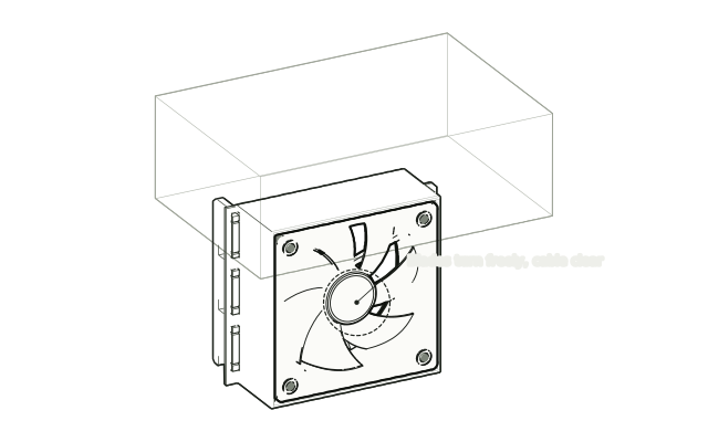 Step 7
Connect and check
Connect the fan to a fan header following its manufacturer’s instructions, check the blades turn freely and nothing touches the graphics card, then power on.
Drawn from the product’s 3D models. Cases, desks, devices and other surroundings are illustrative; drawings are not measured plans.
Care & troubleshooting
Wipe with a soft, slightly damp cloth, then dry. Avoid solvents and hot-water cleaning. If you notice vibration or contact, power down and recheck mounting and cable routing.
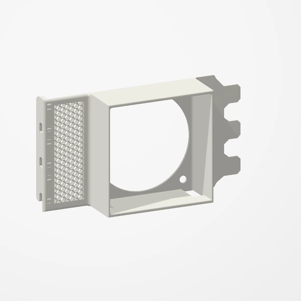
High-Profile 60 mm PCIe Fan Mount
Before you order
- Fan configuration: 1 × 60 mm. Fans are not included.
- Requires 3 free expansion-slot positions.
- High-profile bracket; check the case opening.
- Measure fan thickness and the full assembly clearance beneath the GPU and around nearby cards/cables. Compare with the listing dimensions.
Our tested 1×60 mm configuration reduced GPU temperature by 3°C. GPU fan noise also decreased in our test (not measured in dB). Best suited to tighter cases with limited existing airflow. Results vary by case, hardware, fans and test conditions; temperature and noise improvements are not guaranteed. Check fan thickness and clearance around the GPU. Preview airflow is illustrative.
Setup & use
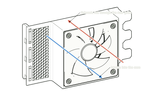 Step 1
Choose intake or exhaust
Decide which way the fan will blow: exhaust pushes warm air out through the rear grille, intake draws cool air in toward the graphics card above.
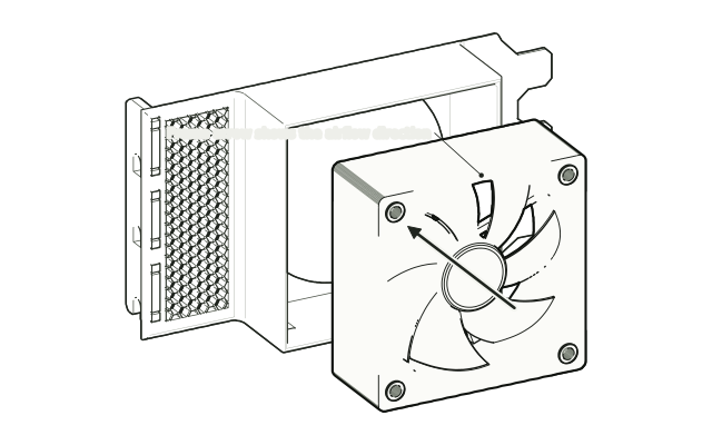 Step 2
Seat the fan
Place the 60 mm fan into the box with the frame arrow pointing the way you chose. A fan is not included.
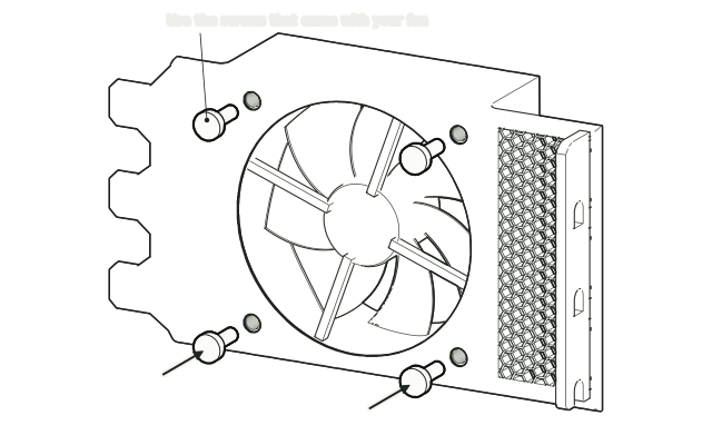 Step 3
Screw it in from the grille side
From the grille side, fix the fan through the four corner holes with the screws (or rubber mounts) that came with it. No screws are included.
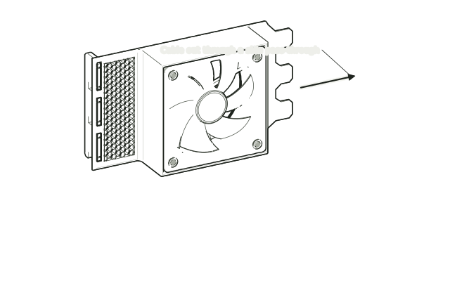 Step 4
Route the cable
Lead the fan cable out through a side pass-through so it stays clear of the blades.
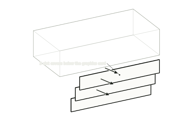 Step 5
Remove the slot covers
Shut down and unplug the PC. Remove the case screws and the 3 slot covers below the graphics card. Keep the screws.
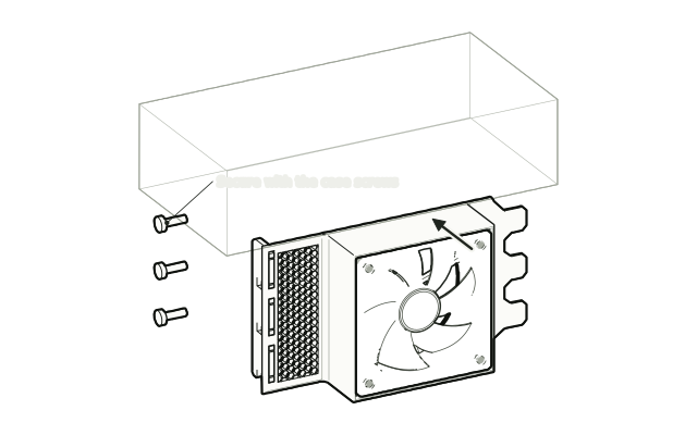 Step 6
Fit it like a card
Slide the mount into the free slots the same way as an expansion card and secure it with the case screws you removed.
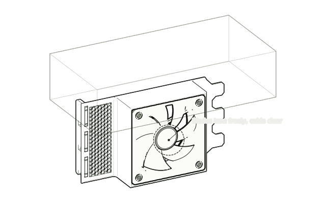 Step 7
Connect and check
Connect the fan to a fan header following its manufacturer’s instructions, check the blades turn freely and nothing touches the graphics card, then power on.
Drawn from the product’s 3D models. Cases, desks, devices and other surroundings are illustrative; drawings are not measured plans.
Care & troubleshooting
Wipe with a soft, slightly damp cloth, then dry. Avoid solvents and hot-water cleaning. If you notice vibration or contact, power down and recheck mounting and cable routing.
Low-Profile 40 mm GPU Fan Mount
Before you order
- Fan configuration: 1 × 40 mm. Fans are not included.
- Requires 2 free expansion-slot positions.
- Low-profile cases supported.
- Measure fan thickness and the full assembly clearance beneath the GPU and around nearby cards/cables. Compare with the listing dimensions.
Best suited to tighter cases with limited existing airflow. Results vary by case, hardware, fans and test conditions; temperature and noise improvements are not guaranteed. Check fan thickness and clearance around the GPU. Preview airflow is illustrative.
Setup & use
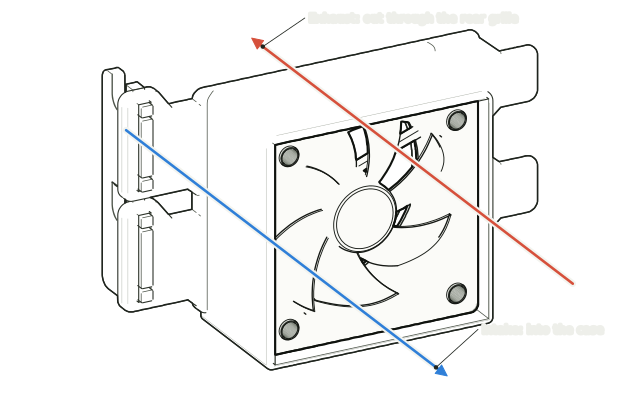 Step 1
Choose intake or exhaust
Decide which way the fan will blow: exhaust pushes warm air out through the rear grille, intake draws cool air in toward the graphics card above.
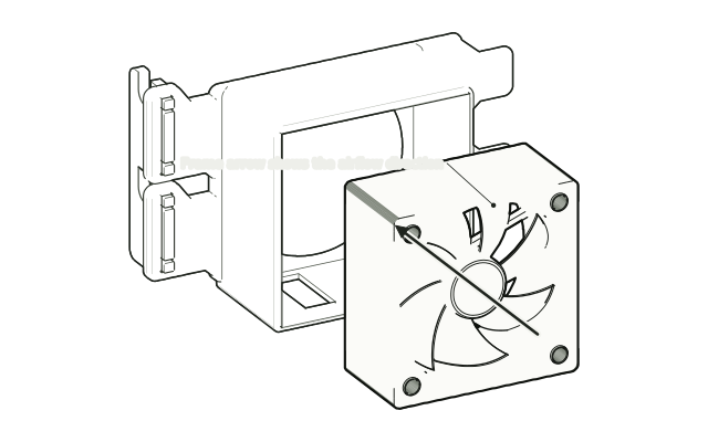 Step 2
Seat the fan
Place the 40 mm fan into the box with the frame arrow pointing the way you chose. A fan is not included.
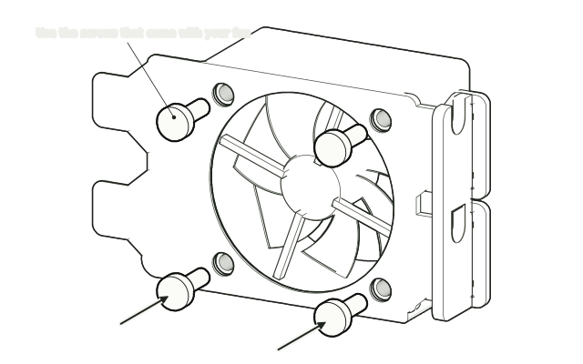 Step 3
Screw it in from the grille side
From the grille side, fix the fan through the four corner holes with the screws (or rubber mounts) that came with it. No screws are included.
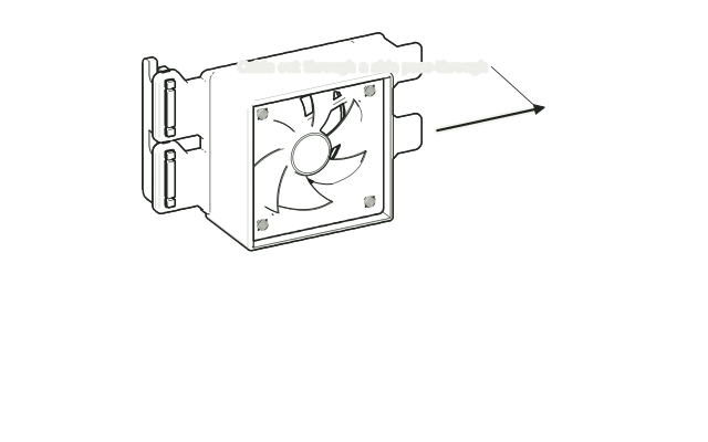 Step 4
Route the cable
Lead the fan cable out through a side pass-through so it stays clear of the blades.
 Step 5
Remove the slot covers
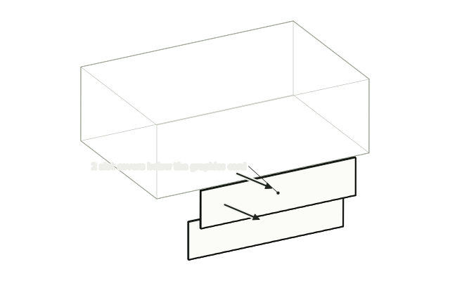
Shut down and unplug the PC. Remove the case screws and the 2 slot covers below the graphics card. Keep the screws.
 Step 6
Fit it like a card
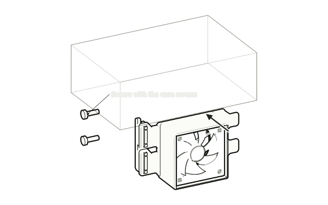
Slide the mount into the free slots the same way as an expansion card and secure it with the case screws you removed.
 Step 7
Connect and check
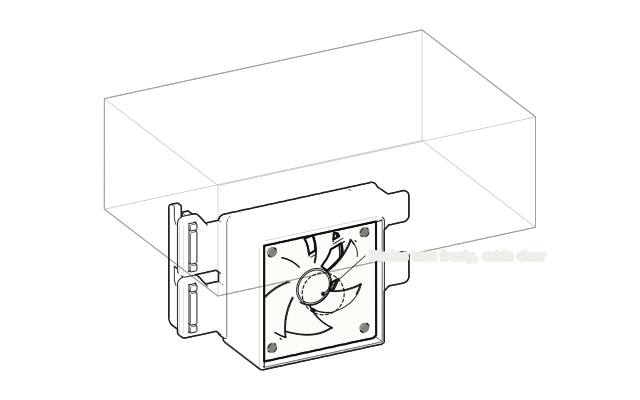
Connect the fan to a fan header following its manufacturer’s instructions, check the blades turn freely and nothing touches the graphics card, then power on.
Drawn from the product’s 3D models. Cases, desks, devices and other surroundings are illustrative; drawings are not measured plans.
Care & troubleshooting
Wipe with a soft, slightly damp cloth, then dry. Avoid solvents and hot-water cleaning. If you notice vibration or contact, power down and recheck mounting and cable routing.
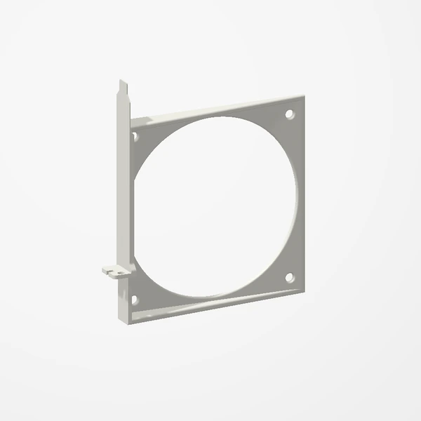
120 mm PCIe Fan Mount
Before you order
- Fan configuration: 1 × 120 mm. Fans are not included.
- Requires 1 free expansion-slot mounting position.
- One mounting position does not mean the whole fan fits within one slot of space.
- Measure fan thickness and the full assembly clearance beneath the GPU and around nearby cards/cables. Compare with the listing dimensions.
Best suited to tighter cases with limited existing airflow. Results vary by case, hardware, fans and test conditions; temperature and noise improvements are not guaranteed. Check fan thickness and clearance around the GPU. Preview airflow is illustrative.
Setup & use
 Step 1
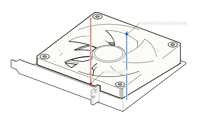
Choose the airflow direction
Decide whether the fan should blow toward the graphics card above it or pull air away from it. Most people exhaust warm air from behind the card.
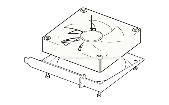 Step 2
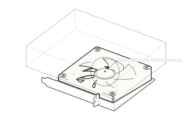
Attach the fan
Lay a 120 × 120 × 25 mm fan on the frame and fix it through the four corner holes with the screws that came with the fan. Screws are not included.
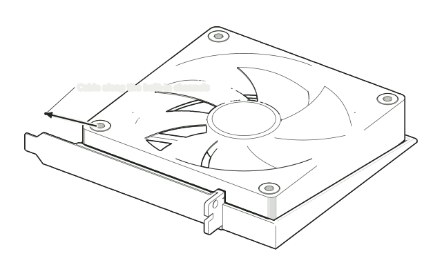 Step 3
Route the cable
Run the fan cable along the frame’s built-in channels so it stays out of the blades.
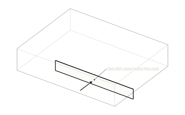 Step 4
Remove one slot cover
Shut down and unplug the PC. Remove one slot cover below the graphics card and keep its thumbscrew.
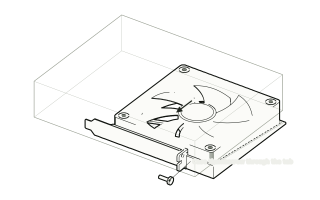 Step 5
Fit it in the slot
Slide the bracket into the free slot like an expansion card and secure it with the case thumbscrew. No tools needed.
 Step 6
Connect and check
Connect the fan to a fan header or hub, check it clears the graphics card and turns freely, then power on.
Drawn from the product’s 3D models. Cases, desks, devices and other surroundings are illustrative; drawings are not measured plans.
Care & troubleshooting
Wipe with a soft, slightly damp cloth, then dry. Avoid solvents and hot-water cleaning. If you notice vibration or contact, power down and recheck mounting and cable routing.
Inside the build
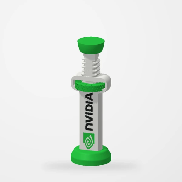
Branded GPU Support
Before you order
- Assembled adjustment: 75–110 mm. Measure your gap at the intended support point.
- Check the base footprint and nearby fan/cable clearance.
Measure the available gap and supporting surface before ordering.
Setup & use
 Step 1
Measure the gap
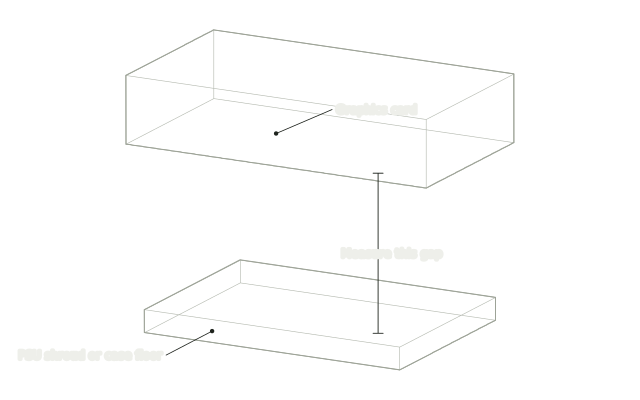
Measure straight down from a support point under the graphics card to the PSU shroud or case floor. This support covers 75–110 mm.
 Step 2
Set it a little short
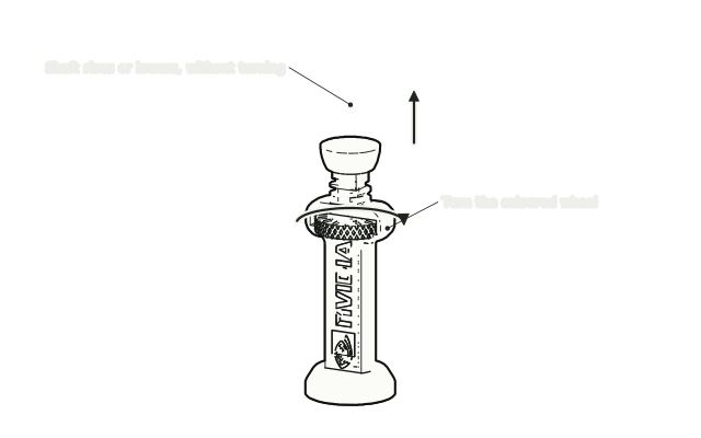
Turn the coloured wheel until the support is slightly shorter than your gap. The shaft and top pad move straight up and down.
 Step 3
Stand it on the shroud
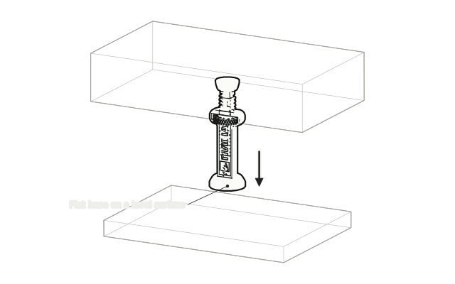
With the PC off, stand the support upright on the PSU shroud or case floor under your support point, with its base flat on a level surface.
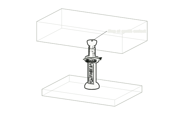 Step 4
Raise it to gentle contact
Turn the wheel until the pad just meets the card. Do not lift or force the card upward.
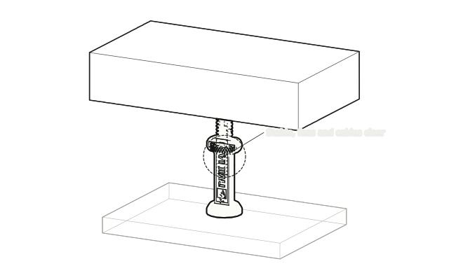 Step 5
Check before powering on
Check the support is upright and steady and that fans and cables are clear, then power on.
Drawn from the product’s 3D models. Cases, desks, devices and other surroundings are illustrative; drawings are not measured plans.
Care & troubleshooting
Wipe with a soft, slightly damp cloth, then dry. Avoid solvents and hot-water cleaning.
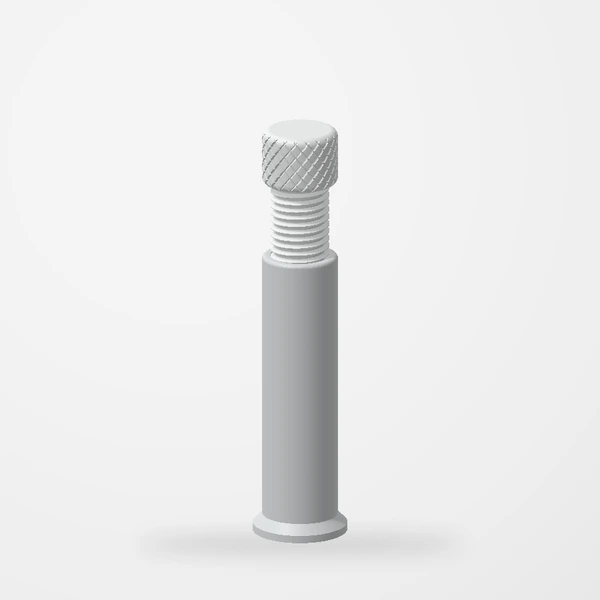
Adjustable GPU Support
Before you order
- Measure vertically from a stable case surface to a suitable support point beneath the GPU.
- Small: 50–70 mm. Large: 70–130 mm, including base-only use at approximately 70 mm (69–73 mm) with the support screw completely unscrewed and removed. Measure your gap and choose the configuration that fits.
- The base magnet holds on a ferrous metal surface that attracts a magnet, as found in many PC cases. Check the actual mounting surface with a magnet.
Choose 50–70 mm or 70–130 mm to suit your measured gap. For the larger option, completely unscrew and remove the support screw to use just the base at approximately 70 mm (69–73 mm). Use the screw for taller positions up to 130 mm; check the chosen configuration against your gap.
Setup & use
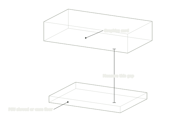 Step 1
Measure the gap
Measure straight down from a support point under the graphics card to the PSU shroud or case floor. The small size covers 50–70 mm, the large 70–130 mm.
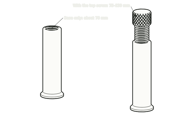 Step 2
Pick the configuration
On the large size, unscrew and remove the top completely for a gap of about 70 mm, or keep it fitted for anything from 75 to 130 mm.
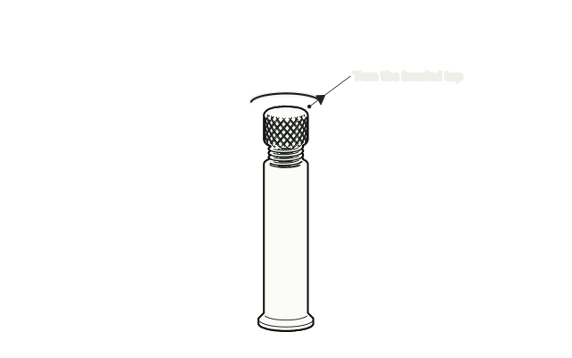 Step 3
Set it a little short
Turn the knurled top until the support is slightly shorter than your gap.
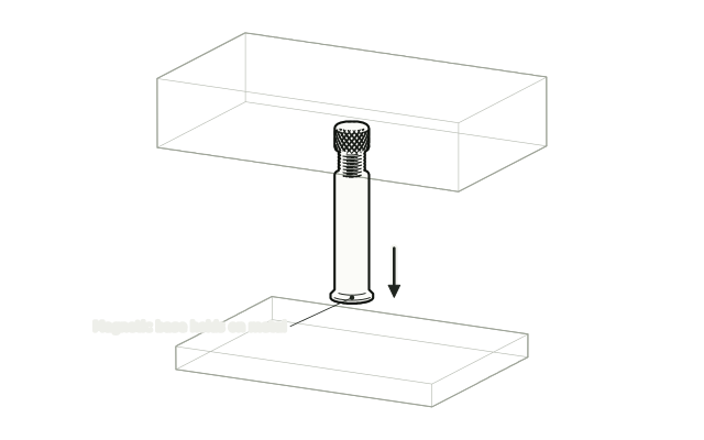 Step 4
Stand it on the shroud
With the PC off, stand the support upright on the PSU shroud or case floor under your support point. The magnet in the base grips metal surfaces.
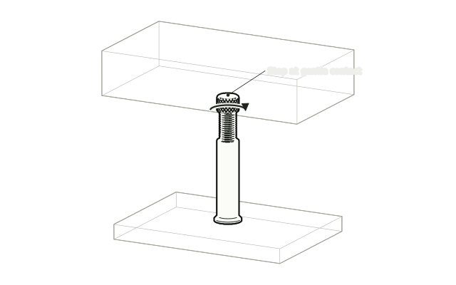 Step 5
Raise it to gentle contact
Turn the top until it just meets the card. Do not lift or force the card upward.
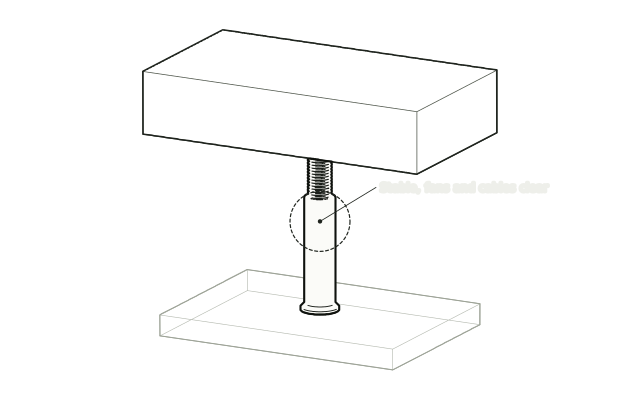 Step 6
Check before powering on
Check that the support stands upright and steady and that the card’s fans and nearby cables are clear, then power on.
Drawn from the product’s 3D models. Cases, desks, devices and other surroundings are illustrative; drawings are not measured plans.
Care & troubleshooting
Wipe with a soft, slightly damp cloth, then dry. Avoid solvents and hot-water cleaning.
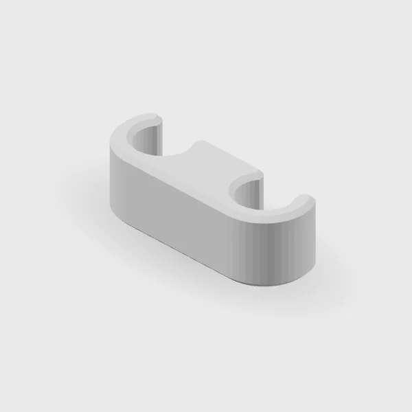
AIO Radiator Comb & Clip
Before you order
- Measure the outside diameter of the tubing, including its sleeve.
- Measure the spacing between the tubes where the clip will sit.
- The combs snap onto the tubing of most consumer AIO coolers; no one has reported a sizing problem.
Check the fit against your tubing before ordering.
Setup & use
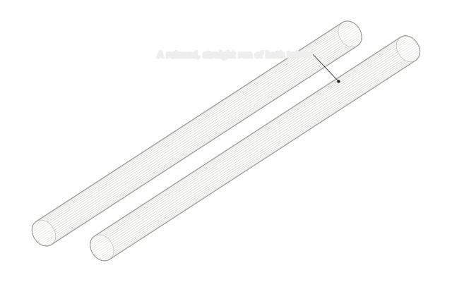 Step 1
Pick a straight run
With the PC off, choose a relaxed, straight section of the two AIO tubes, clear of the pump and radiator fittings.
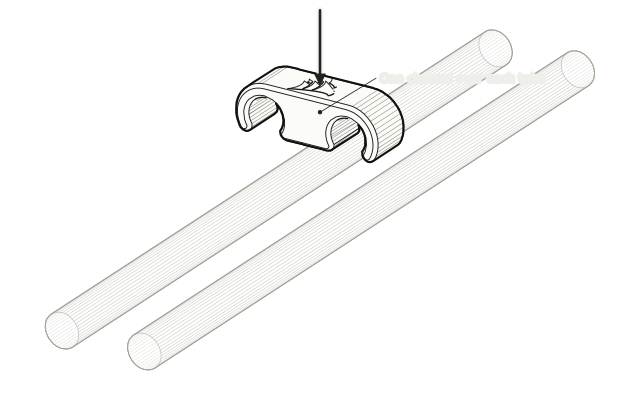 Step 2
Line it up over both tubes
Hold the comb over the tubes with one channel above each tube.
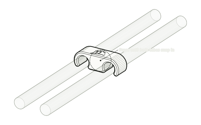 Step 3
Press it on
Press the comb down until both tubes snap into their channels. It fits most consumer AIO tubing snugly.
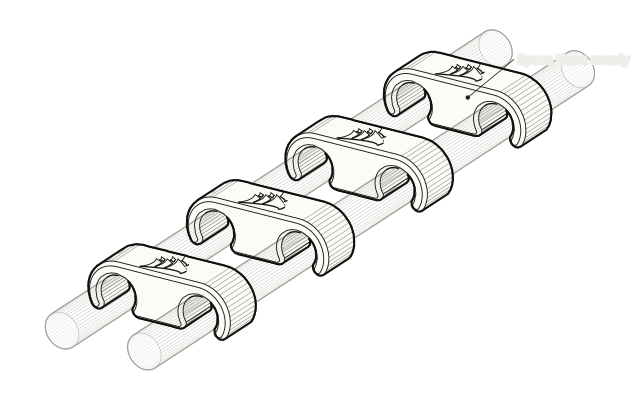 Step 4
Space them evenly
Fit the rest of the combs along the tubes with even gaps, then check no tube is pinched, kinked or pulled tight.
Drawn from the product’s 3D models. Cases, desks, devices and other surroundings are illustrative; drawings are not measured plans.
Care & troubleshooting
Wipe with a soft, slightly damp cloth, then dry. Avoid solvents and hot-water cleaning. Remove and reassess the fit if the clip compresses the tubing.
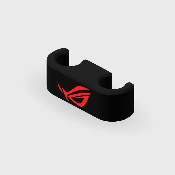
ASUS Red-Logo AIO Clip
Before you order
- Measure the outside diameter of the tubing, including its sleeve.
- Measure the spacing between the tubes where the clip will sit.
- The combs snap onto the tubing of most consumer AIO coolers; no one has reported a sizing problem.
Check the fit against your tubing before ordering.
Setup & use
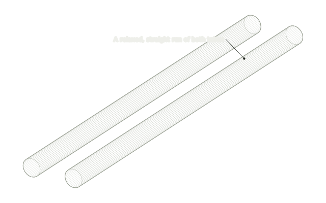 Step 1
Pick a straight run
With the PC off, choose a relaxed, straight section of the two AIO tubes, clear of the pump and radiator fittings.
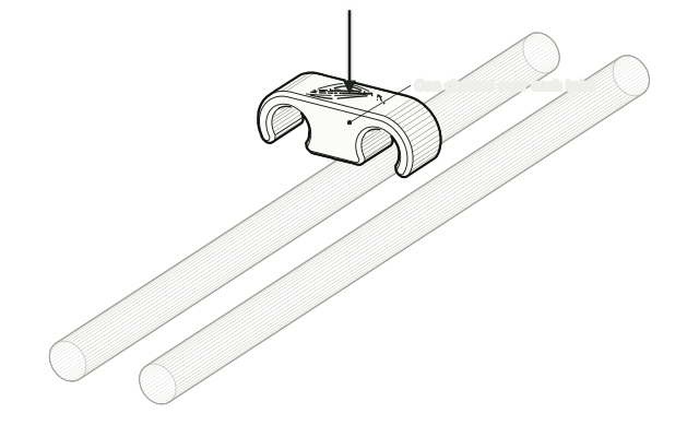 Step 2
Line it up over both tubes
Hold the comb over the tubes with one channel above each tube.
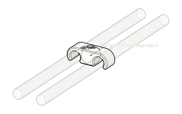 Step 3
Press it on
Press the comb down until both tubes snap into their channels. It fits most consumer AIO tubing snugly.
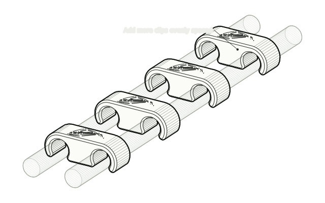 Step 4
Space them evenly
If you are fitting more than one, space them evenly, then check no tube is pinched, kinked or pulled tight.
Drawn from the product’s 3D models. Cases, desks, devices and other surroundings are illustrative; drawings are not measured plans.
Care & troubleshooting
Wipe with a soft, slightly damp cloth, then dry. Avoid solvents and hot-water cleaning. Remove and reassess the fit if the clip compresses the tubing.
Desk & setup
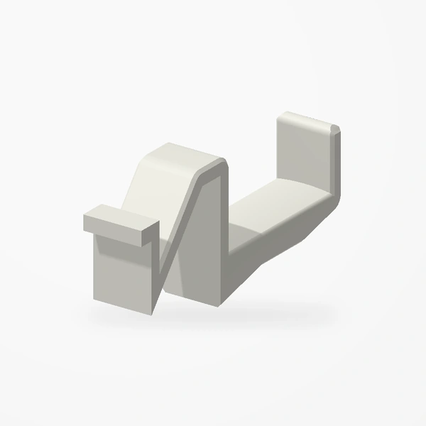
Corsair 5000D / 5000X Headphone Holder
Before you order
- Designed for the Corsair 5000D / 5000X case family.
- It hooks under the edge of the top grille, beside the removable magnetic top dust filter, and hangs down the side panel.
The off-white holder is the product. Its hook slips through the gap beside the top exhaust grille and catches beneath the grille edge, beneath the removable top dust filter. The case and Razer BlackShark V2 headphones are illustrative and are not included. See Etsy for available colors.
Setup & use
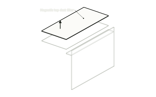 Step 1
Lift off the top dust filter
Lift the magnetic dust filter off the top of the case. The holder can be slid in with it fitted, but it is easiest with the filter off.
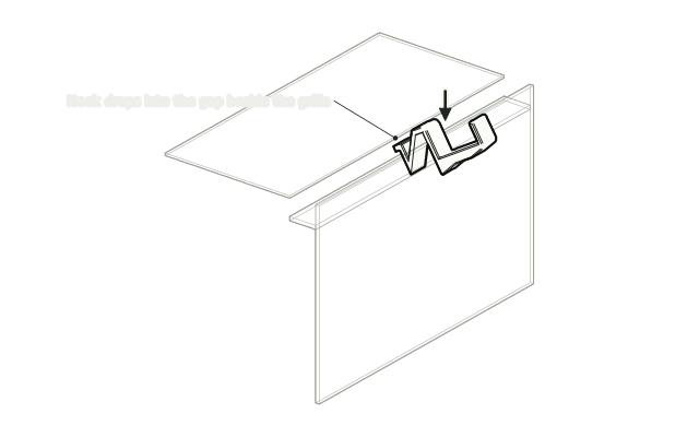 Step 2
Hook it under the grille edge
Drop the hook into the gap beside the top grille so its tab catches under the grille edge.
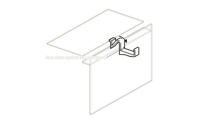 Step 3
Swing it down
Swing the arm down so it rests against the side panel.
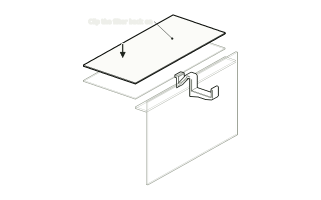 Step 4
Clip the filter back on
Put the dust filter back on top. It holds the hook in place.
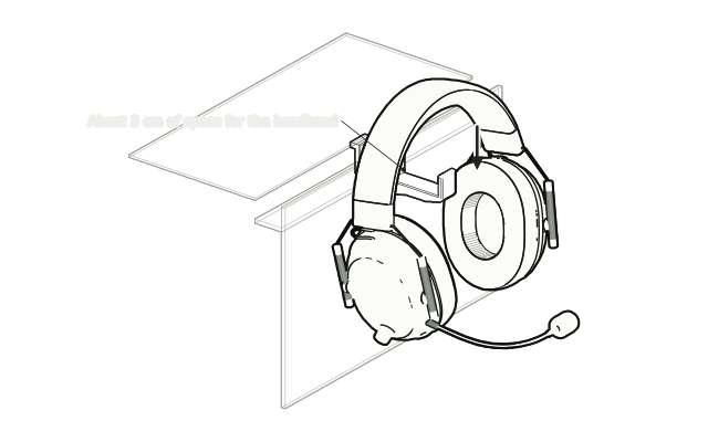 Step 5
Hang your headphones
Rest the headband across the hook. There is about 5 cm of space, enough for most headsets.
Drawn from the product’s 3D models. Cases, desks, devices and other surroundings are illustrative; drawings are not measured plans.
Care & troubleshooting
Wipe with a soft, slightly damp cloth, then dry. Avoid solvents and hot-water cleaning.
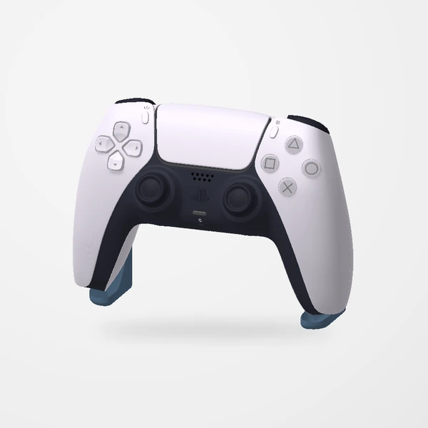
DualSense Controller Stand
Before you order
- Designed around a DualSense controller.
- Allow space for the complete controller and any connected cable. Controller not included.
The blue-gray stand is the product. Controller shown for fit and scale; not included. See Etsy for available colors.
Setup & use
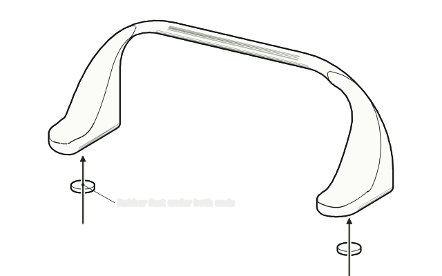 Step 1
Stick on the rubber feet
Peel and stick a rubber foot under each end of the stand so it sits without wobbling.
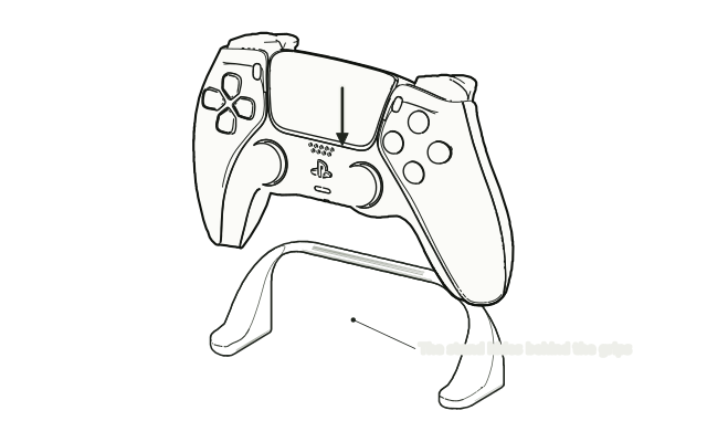 Step 2
Lower the controller on
Set the stand on a flat surface and lower your DualSense onto it so the grips straddle the arch.
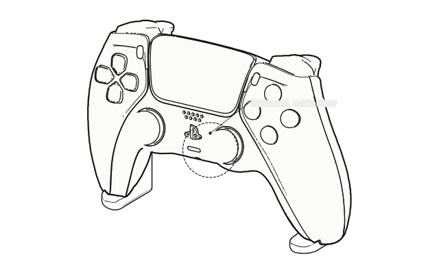 Step 3
Check the balance
Check the controller sits level and steady, and that any connected cable is not pulling on it. Controller not included.
Drawn from the product’s 3D models. Cases, desks, devices and other surroundings are illustrative; drawings are not measured plans.
Care & troubleshooting
Wipe with a soft, slightly damp cloth, then dry. Avoid solvents and hot-water cleaning.
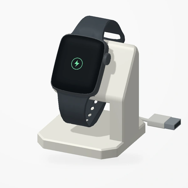
Apple Watch Stand
Before you order
- Compare the charging puck supplied with your watch with the recess dimensions in the listing.
- Check watch/band clearance. Watch, charging puck and cable are not included.
The off-white stand is the product. Apple Watch, magnetic charging puck and cable are not included. Check your charger and band against the Etsy listing before ordering.
Setup & use
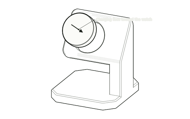 Step 1
Seat the charging puck
Press your Apple Watch charging puck into the recess with its charging face outward. It should fit the recess without force.
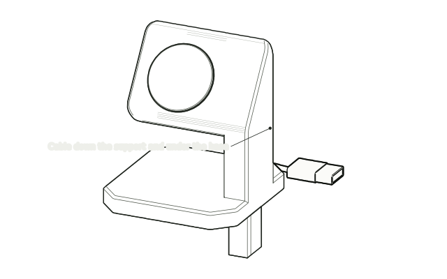 Step 2
Route the cable
Lead the cable down through the support and out under the base.
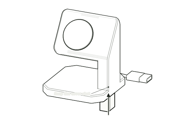 Step 3
Snap the cover shut
Close the removable cover over the cable so it is held without being pinched.
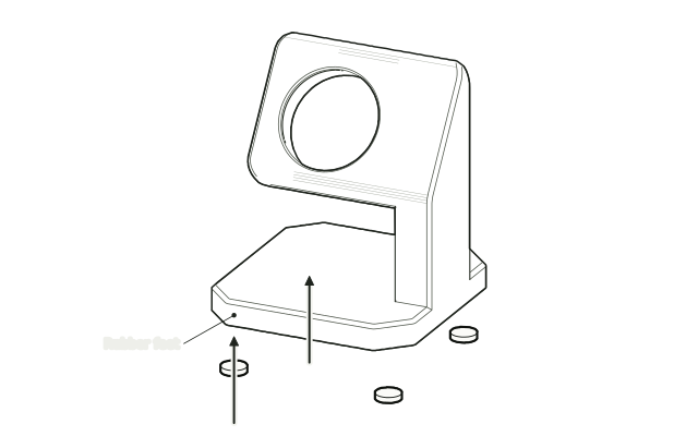 Step 4
Stick on the rubber feet
Stick the rubber feet under the base, then set the stand on a flat surface and connect your charger.
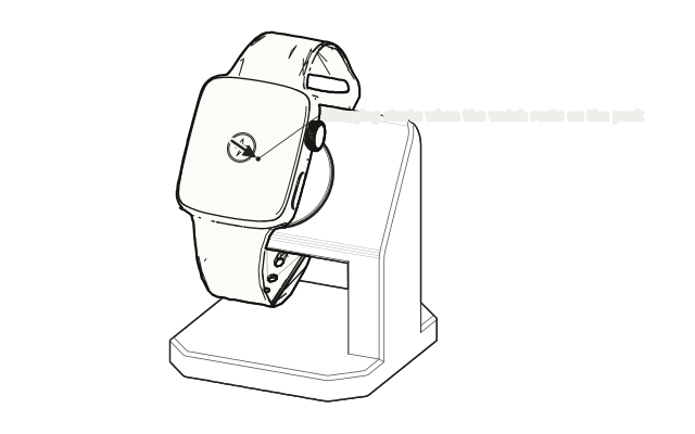 Step 5
Rest the watch on the puck
Rest the back of the watch on the puck, check the band clears the stand, and confirm it starts charging.
Drawn from the product’s 3D models. Cases, desks, devices and other surroundings are illustrative; drawings are not measured plans.
Care & troubleshooting
Wipe with a soft, slightly damp cloth, then dry. Avoid solvents and hot-water cleaning. Remove the charger before cleaning; follow Apple’s charger instructions.
Model sources: Apple Watch Stand by Aeonfly (supplied print profile: Vacchi, BY-SA). Apple Watch SE by Valentine_crut, CC BY 4.0; band pose and materials adapted for this preview. Charger and cable are illustrative models. Full preview credits.
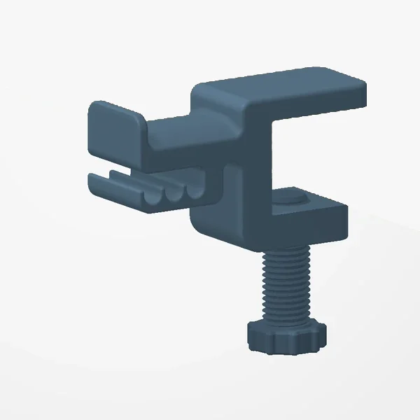
Desk Clamp Headphone Holder
Before you order
- Measure the desk-edge thickness and unobstructed depth below the edge.
- The jaw is made very deep, so it fits practically any desk thickness.
Check your desk-edge clearance before ordering. The preview uses an illustrative 25 mm desk and Razer BlackShark headphones; headphones are not included.
Setup & use
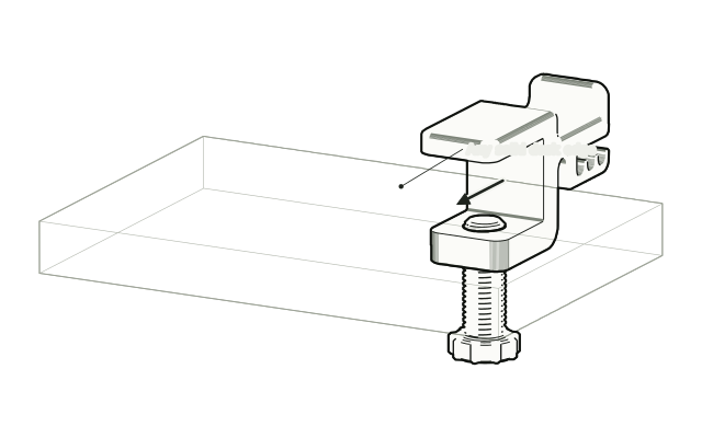 Step 1
Slide it onto the desk edge
Open the clamp and slide it onto a solid desk edge. The jaw is made very deep, so it fits practically any desk.
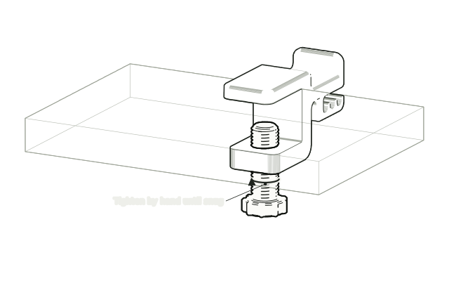 Step 2
Tighten the screw by hand
Turn the screw under the desk until the clamp holds firmly. Hand-tight is enough.
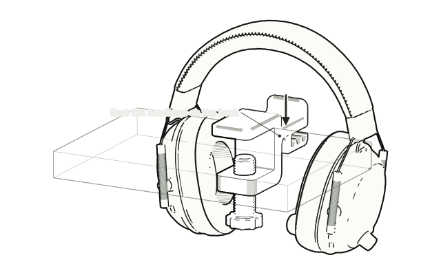 Step 3
Hang your headphones
Lower your headphones onto the hook so the headband rests across it, and check the clamp stays put.
Drawn from the product’s 3D models. Cases, desks, devices and other surroundings are illustrative; drawings are not measured plans.
Care & troubleshooting
Wipe with a soft, slightly damp cloth, then dry. Avoid solvents and hot-water cleaning. Recheck the clamp periodically. Stop using it if the part loosens or cracks.
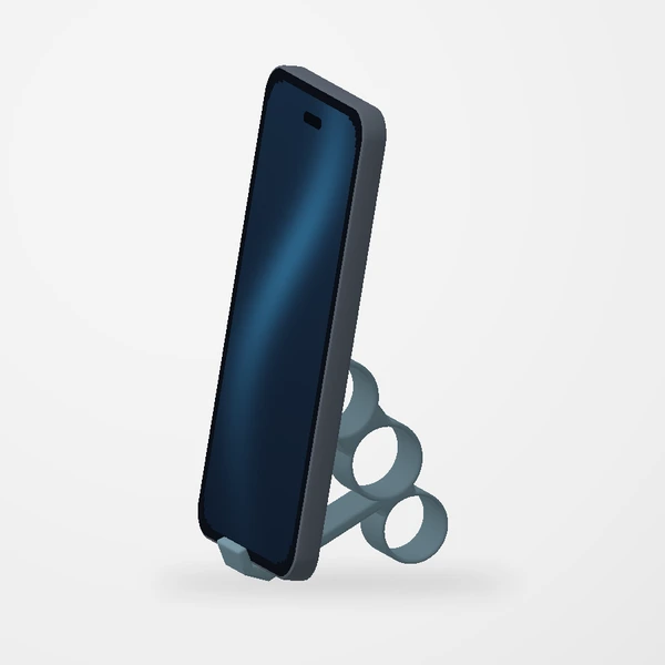
Pinky Saver Phone Grip
Before you order
- Check the selected grip size against your fingers and phone with its case fitted.
- The website preview uses the supplied Large model; the illustrated phone does not establish universal compatibility.
Preview uses the supplied large model. Phone shown for scale and stand placement; not included. See Etsy for available colors.
Setup & use
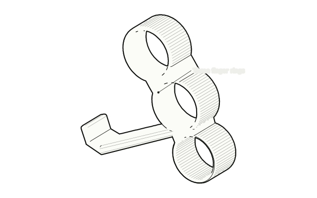 Step 1
Slip your fingers through
Slide three fingers of your holding hand through the rings, with the lip toward the phone.
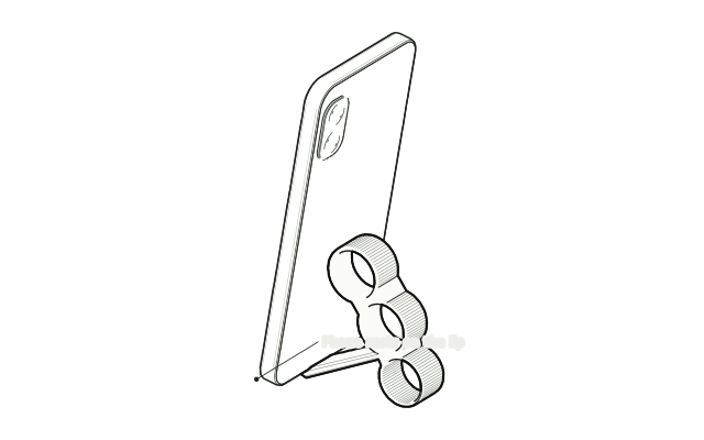 Step 2
Rest the phone on the lip
Rest the bottom edge of the phone on the lip and hold it as normal. The grip takes the weight off your pinky.
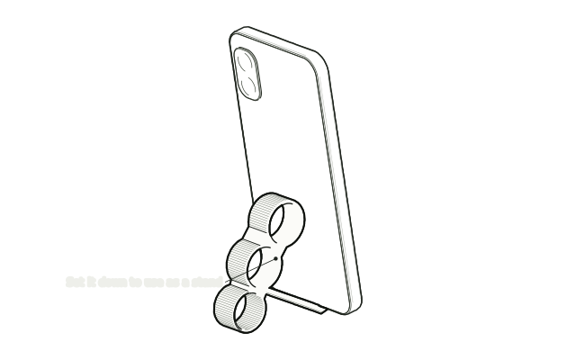 Step 3
Use it as a stand
Set the grip down on a flat surface with the phone leaning back on it for videos and calls.
Drawn from the product’s 3D models. Cases, desks, devices and other surroundings are illustrative; drawings are not measured plans.
Care & troubleshooting
Wipe with a soft, slightly damp cloth, then dry. Avoid solvents and hot-water cleaning.
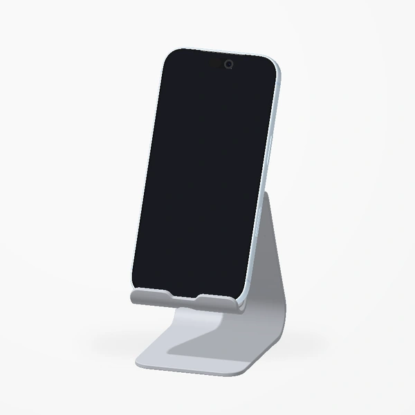
Minimal Smartphone Stand
Before you order
- Check phone thickness with its case fitted against the cradle opening in the listing.
- Check the charging connector and cable have clearance. Phone and cable not included.
The silver stand is the product. Shown with iPhone 18 Pro for scale and fit; phone and cable are not included. See Etsy for available colors.
Setup & use
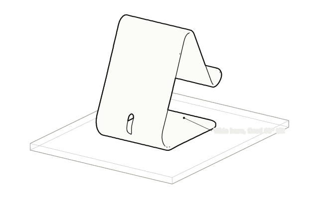 Step 1
Place it on a level surface
Set the stand on a flat desk or nightstand. The wide base keeps it steady.
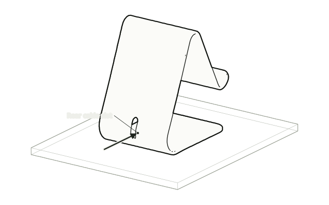 Step 2
Feed the cable through the slot
Pass your charging cable through the rear slot and bring the connector up to the cradle.
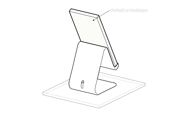 Step 3
Rest your phone in the cradle
Connect the cable and rest the phone in the cradle, upright or sideways. Phone and cable are not included.
Drawn from the product’s 3D models. Cases, desks, devices and other surroundings are illustrative; drawings are not measured plans.
Care & troubleshooting
Wipe with a soft, slightly damp cloth, then dry. Avoid solvents and hot-water cleaning.
Model sources: Minimalist Stand Phone by alainpoli147 (CC BY-SA). Apple iPhone 18 Pro Glacier 2026 by extraakash; materials adapted for this preview. Full preview credits.
Everyday carry
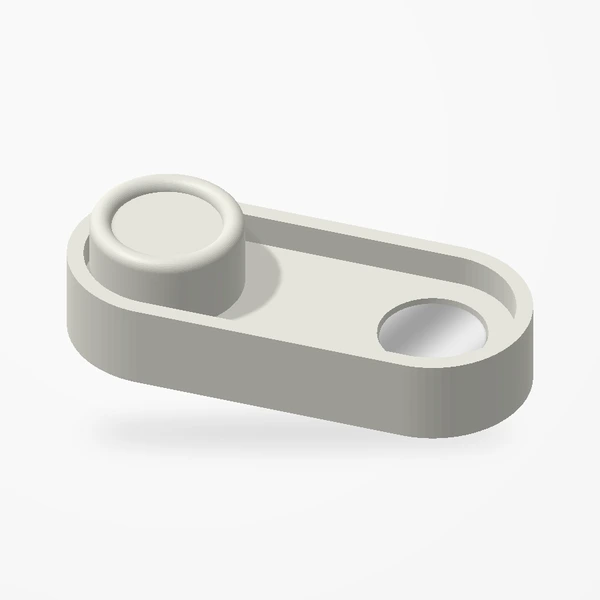
Magnetic Fidget Slider
Before you order
- Choose Small, Medium or Large from the dimensions in the Etsy listing.
- The three sizes each have their own action and 360° views; render framing is not a scale comparison.
Three neodymium magnets: one beneath the puck and one at each end of the tray. Choose Small, Medium or Large; see Etsy for available colors. The on-screen snap cue illustrates the magnetic engagement.
Setup & use
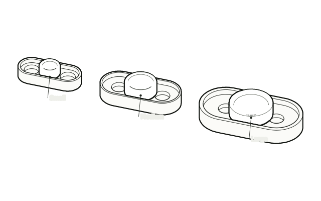 Step 1
Pick your size
Small, Medium and Large slide the same way; choose the size that suits your hand.
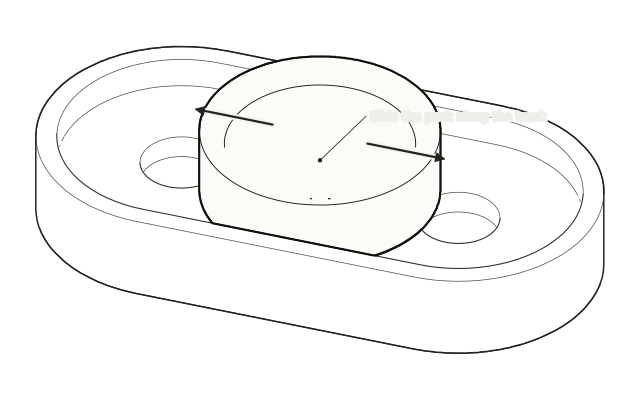 Step 2
Slide the puck
Push the puck along its track with a fingertip.
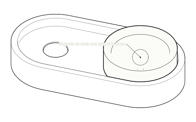 Step 3
Feel it snap
At each end, the magnet in the tray and the one under the puck pull it in with a snap. Slide it back to repeat.
Drawn from the product’s 3D models. Cases, desks, devices and other surroundings are illustrative; drawings are not measured plans.
Care & troubleshooting
Wipe with a soft, slightly damp cloth, then dry. Avoid solvents and hot-water cleaning. Keep the track free of debris. Stop use if a magnet becomes loose; keep loose magnets away from children.
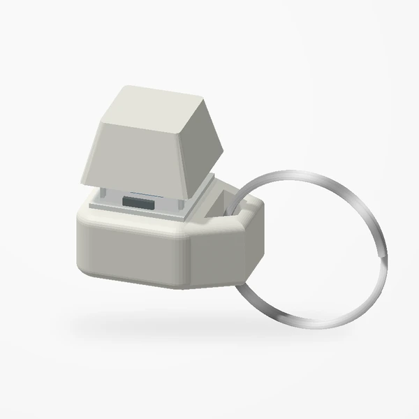
Clicky Fidget Keychain
Before you order
- Choose one, two or three keys; each version has an attached metal keyring.
- Gateron Blue switches provide the click. The preview illustrates the switch housing and actuation.
Choose one, two or three keys, each with an attached metal keyring. Premium PETG-HF base and keycaps; see Etsy for colors. The visual click cue marks switch actuation. Switch housings are illustrated from product references.
Setup & use
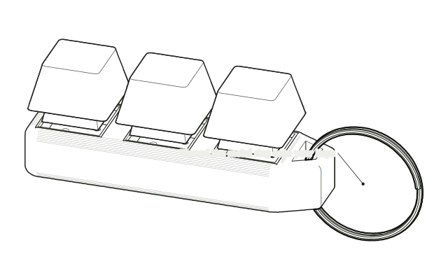 Step 1
Add it to your keys
Open the metal split ring and thread it onto your keyring. Avoid levering the body sideways.
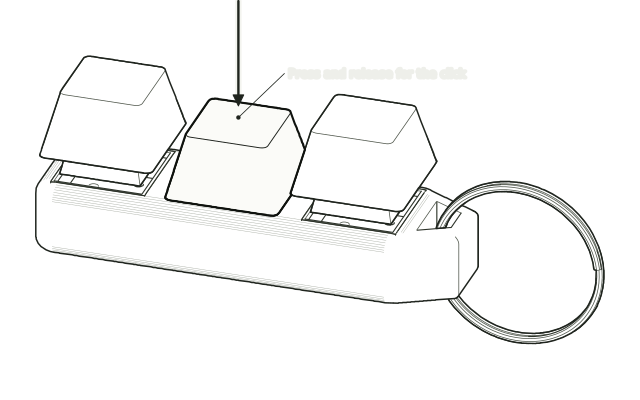 Step 2
Press the keys
Press and release each key like a keyboard key. The Gateron Blue switches give the click.
Drawn from the product’s 3D models. Cases, desks, devices and other surroundings are illustrative; drawings are not measured plans.
Care & troubleshooting
Keep liquid away from the switches. Clean the outside with a dry, soft cloth. Check the loop and ring periodically; stop use if damaged.
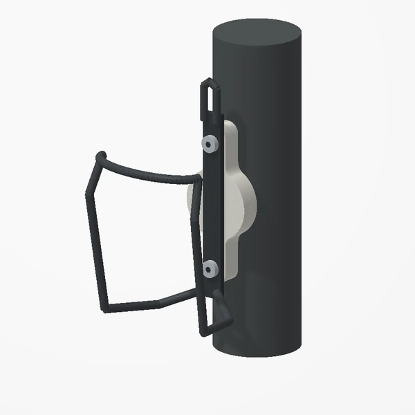
Bicycle Tracker Mount
Before you order
- Choose AirTag or UGREEN FineTrack to match the tracker you own.
- Mounting-hole spacing: 65 mm, measured centre to centre. Two M5 screws included.
- Check bottle-cage, frame and screw engagement clearance. Tracker, cage and bicycle not included.
Choose the holder made for your tracker. Fits 65 mm mounting spacing; two M5 screws included. Check frame and bottle-cage clearance before ordering. Tracker, bottle cage and bicycle are not included. The off-white enclosure is the product; bicycle context is illustrative.
Setup & use
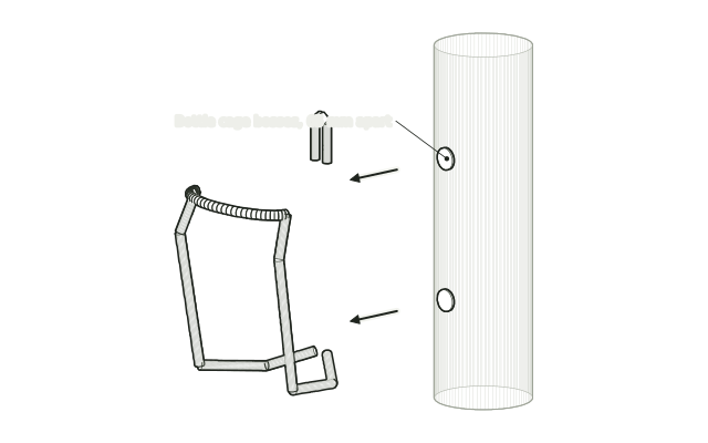 Step 1
Take off the bottle cage
Remove the bottle cage and its screws from the frame’s bottle-cage bosses.
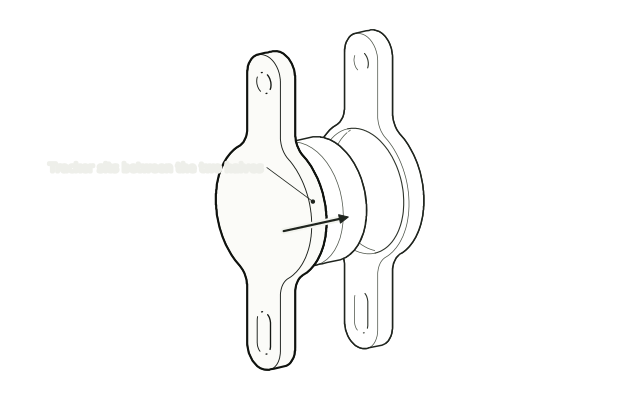 Step 2
Put the tracker in
Place your AirTag or UGREEN FineTrack in the holder and lay the other half over it. The screws will clamp the halves together.
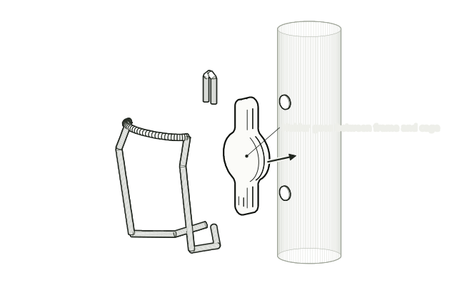 Step 3
Stack holder and cage
Line up the holder’s slots with the bosses and place the bottle cage back over it.
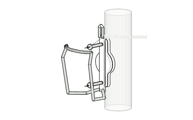 Step 4
Fit the two M5 screws
Fit the two included M5 screws through the cage and holder into the bosses and tighten them. Their clamping force holds the two halves shut.
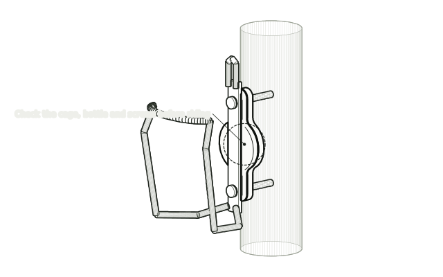 Step 5
Check before riding
Follow your bicycle maker’s tightening guidance, then check the cage, bottle and screws are secure before riding.
Drawn from the product’s 3D models. Cases, desks, devices and other surroundings are illustrative; drawings are not measured plans.
Care & troubleshooting
Wipe with a soft, slightly damp cloth, then dry. Avoid solvents and hot-water cleaning. Inspect attachment regularly and after impacts. The holder does not guarantee theft prevention.
Shopping & orders
Start here for finished products and purchases.
Where can I buy your products?
Shop finished products at BANKASI [creations] on Etsy. Our Creations page lets you explore the designs before opening the shop.
How do I choose the right size?
Check the dimensions and options in the Etsy listing against your setup. Our 40 mm PCIe fan mounts need two free slots; the 60 mm mounts need three. Low-profile versions support low-profile cases with that slot clearance. Fans are not included. For PC parts, measure the available clearance and check nearby components. If you are unsure, send us your measurements and the product you are considering.
Where can I find shipping times and delivery options?
The Etsy listing and checkout show the available delivery options for your address. Check those details before ordering, as availability and estimated dates can vary.
Something wrong with your order?
We’re sorry it isn’t right, and we want to fix it. Message us through your Etsy order: it’s the fastest way to reach us and keeps everything connected to your purchase.
- Arrived damaged or a part is missing: include a photo of the part and the packaging.
- Doesn’t fit: tell us your case, desk or device and the measurement you took. The Fit checks in your product’s guide above can help too.
- Wrong item, or ordered by mistake: let us know which item you received or meant to order.
Returns, exchanges and cancellations
- Returns and exchanges are accepted within 30 days.
- The buyer is responsible for return shipping costs, and for any loss in value if an item isn’t returned in its original condition.
- Cancellations can be requested within 2 hours of purchase.
The same policy is shown on each listing in our Etsy shop.
How do I get help with an existing order?
Message BANKASI [creations] through your Etsy order so the conversation stays connected to your purchase. Include your question and, if relevant, a photo of the issue.
Designs & materials
Get to know the parts before adding them to your setup.
What do you make?
We design PC and desk accessories manufactured from premium PETG-HF for thermal resistance and structural durability, including adjustable GPU supports, fan mounts, AIO tubing clips, and headphone holders. Explore them in the collection.
Can I download the model files?
The Creations page provides interactive previews. Model files are not available for download. You can buy finished products on Etsy or ask us about a design.
Can you make a custom part or help with a PC build?
Contact us to discuss your project. Include what you want to make, the relevant dimensions or hardware, and any reference photos. We can review the request and discuss what is possible.
YouTube & collaborations
Questions about the channel and working together.
Can I suggest a product or video idea?
Yes. Tell us what you would like to see and what interests you about it. We consider suggestions when planning future videos.
Are your reviews sponsored?
Some reviews may be sponsored. We disclose sponsorships and are committed to honest, independent evaluations.
How can a brand get in touch?
Start at Work with us: our audience figures, the parts we have made to order and a partnership form. You can also use our contact form with a short introduction, the product or project, and what you have in mind.
Can I send you my old tech?
Yes, free of charge. Phones, laptops, PC parts, peripherals, consoles and most other unwanted tech and e-waste that fits in one box up to 25 lb, working or broken, shipped from within the United States. Tell us what you have on Old tech; we reply by email with a shipping address and reimburse your standard ground shipping through PayPal once you send the receipt or invoice for the label. Please don't ship anything before we reply.
Is there a place to talk with other builders?
Yes. Join the discussion on our forum. Bankasi Creations Help covers fit questions, installation help and product feedback; Community Showcase is for your setup or latest print; and PC Builds & Hardware, 3D Printing & Making and Videos & Workbench cover the rest. Keep order and personal details off the forum: for anything about an order, contact us directly.
About Bankasi
The people and place behind the projects.
What is Bankasi Media?
Founded by Marwan Ibrahim in 2024, Bankasi Media brings together hardware videos, build projects, and original accessories. Read our story for more about the studio.
Where are you based?
We are based in New York and share our work online with viewers and customers around the world. For product delivery availability, check the relevant Etsy listing.
How can I contact you?
Send a message through our contact page. For an existing Etsy purchase, message us through the order so we have its details.
No matching answers yet
Try a shorter search, browse a topic, or send us your question.
ASK US DIRECTLY
Need a hand with something specific?
Tell us about your setup or project so we can point you in the right direction.